Home

לשפץ התמדה בקלילות robot tool frame 4points סגסוגת צוק סרט צילום

Easy industrial robot cell coordinates calibration with touch panel -  ScienceDirect
Easy industrial robot cell coordinates calibration with touch panel - ScienceDirect

General Tips - RoboDK Documentation

IET 375 HW 3 Solution_Spring 2019.pdf - IET 375 Robotics IET 375 HW 3  Solutions (Total 36 Points) 1. (12 points) A user tool frame UT[k] is set  up for a | Course Hero
IET 375 HW 3 Solution_Spring 2019.pdf - IET 375 Robotics IET 375 HW 3 Solutions (Total 36 Points) 1. (12 points) A user tool frame UT[k] is set up for a | Course Hero

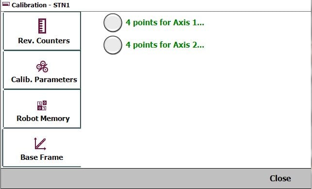
Calibrate Turn-/Tilt-Table with 4 points for 2 axes — ABB Robotics User  Forums
Calibrate Turn-/Tilt-Table with 4 points for 2 axes — ABB Robotics User Forums

Creating a Tool Frame Using the Three Point Method - YouTube

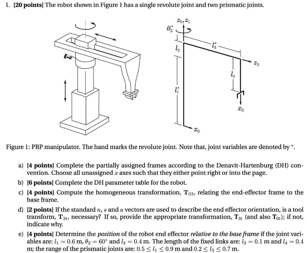
Solved 1. [20 points) The robot shown in Figure 1 has a | Chegg.com

Applied Sciences | Free Full-Text | Research of Calibration Method for  Industrial Robot Based on Error Model of Position
Applied Sciences | Free Full-Text | Research of Calibration Method for Industrial Robot Based on Error Model of Position

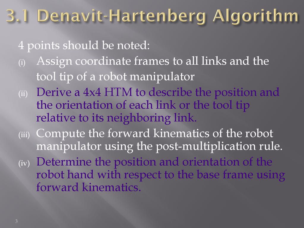
CHAPTER 2 FORWARD KINEMATIC ppt download

General Tips - RoboDK Documentation

Robot Tool Center Point Calibration using Computer Vision

Understanding Robot Coordinate Frames and Points

ABB Robot Tutorial: Defining Tool Frames and Basic Modeling in Robot Studio  - YouTube
ABB Robot Tutorial: Defining Tool Frames and Basic Modeling in Robot Studio - YouTube

Coordinate System Frames in Industrial Robots » Patti Engineering

TOOL FRAMES IN FANUC'S ROBOGUIDE SOFTWARE - YouTube

The left picture shows the robot arm grasping a tethered tool. The... |  Download Scientific Diagram
The left picture shows the robot arm grasping a tethered tool. The... | Download Scientific Diagram

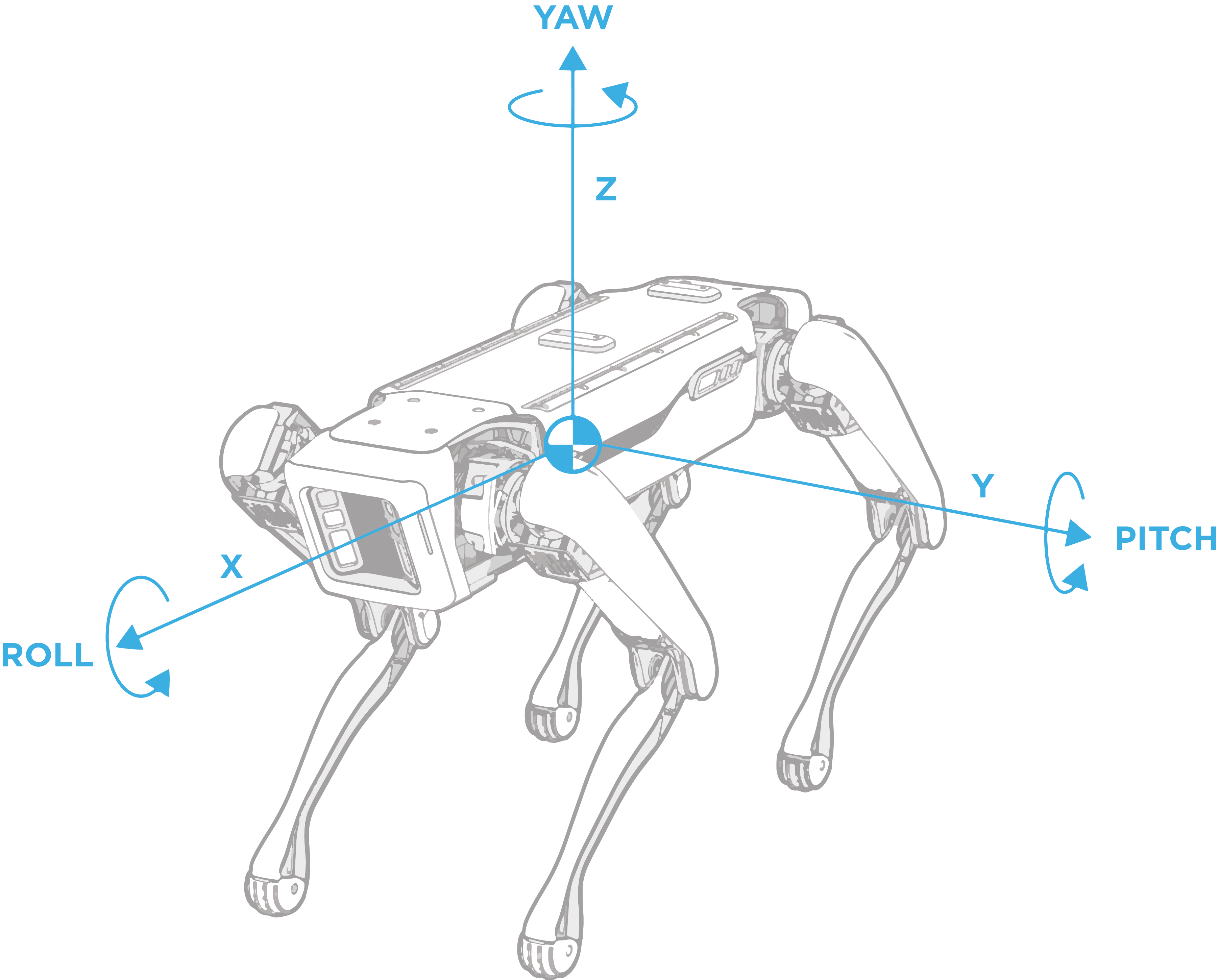
Geometry and Frames — Spot 3.2.2.post1 documentation

General Tips - RoboDK Documentation

Understanding Robot Coordinate Frames and Points

Robot Tool Center Point Calibration using Computer Vision

Understanding Robot Coordinate Frames and Points

Programming FANUC® Robots for Industry Applications Sample Chapter by  American Technical Publishers - Issuu
Programming FANUC® Robots for Industry Applications Sample Chapter by American Technical Publishers - Issuu

Schematic system representation and definition of various coordinate... |  Download Scientific Diagram
Schematic system representation and definition of various coordinate... | Download Scientific Diagram

General Tips - RoboDK Documentation

FANUC Setup Frame Configuration - Setting Up User Tool - DIY Robotics

FlexiExpert
FlexiExpert

Lab 2 TOOL Frame Set Up